The „Next Generation Train“ (NGT) is a guiding concept for transportation research at the German Aerospace Center (DLR). This lightweight, high-speed double-deck train serves as a framework for the development of concepts, methods and technologies for future rail transport. The running gear design plays an essential role in this framework.
In virtual design, simulation and M 1:5 experiments, a structurally optimized single wheel pair bogie with independently rotating wheels using mechatronic guidance and direct drive motors close to the wheels has shown promising results. It offers the capability of almost perfect steering along curves and facilitates level floors even on the lower level of a double-deck car. In the current development step, a functional M 1:1 prototype of the NGT running gear is being built and will be made available as the NGT running gear research facility (FuN) for DLR internal and external research activities. Starting in 2024, FuN will be operated for three years in two annual measurement campaigns on external rolling test rigs. In addition, further testing in a rail vehicle on test and inspection facilities is planned.
Project Objectives
- Validation and demonstration of the three basic innovations for rail vehicle running gears proposed in the NGT project, namely
-
mechatronic track guidance,
-
lightweight construction and
-
gearless direct drives close to the wheels
-
- Advancing NGT project results to technology readiness level (TRL) 6
- Installation of a facility for research tasks in predictive maintenance, life-cycle cost reduction, automation and mechatronics.
Technologies of the NGT Running Gear
Mechatronic Guidance
Conventional track guidance in today's railway bogies is based on the passive stability properties of wheelsets, in which the two profiled wheels are connected to a shaft that couples the rotating speed of the two wheels.
However, the active control of the two individually driven wheels realized in the NGT running gear makes it possible to freely determine the position of the wheel pair in the track channel, to radially adjust its alignment in the track curve, to counteract track position disturbances, and to realize new mechatronic functions such as control of the wear profile. Since the wheelset shaft is eliminated in this mechatronic track guidance system, level passage without steps is possible in double-deck cars, even on the lower level.
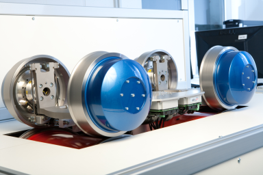 M 1:5 experimental running gear with mechatronic guidance
Lightweight design
The consistent lightweight design, supported by computer-aided structural optimization, allows the realization of a driven running gear at the weight level of a trailer bogie. This increases the payload capacity while the wheel loads remain the same or vice versa, reduces the wheel loads while the payload remains the same. This way, the usage of material resources is reduced in production, less energy is required in operation for acceleration and deceleration of the tare masses, and life cycle costs are reduced.
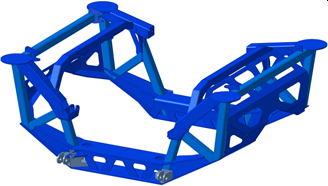 CAD-Model of the structurally optimized lightweight design of the running gear frame
Direct drives close to the wheel
Permanently excited synchronous motors with high torque density and efficiency are used as drives, so that the lightweight design advantages described above also have an impact on life cycle costs. The motors are rubber-sprung and mounted on the wheel carrier so that they are decoupled from high-frequency rail irregularities and the unsprung masses are reduced as much as possible. The direct, i.e. gearless, couplings of the motors to the wheels consist of connecting links and are torsionally stiff but capable of compensating the spring deflections.
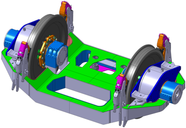 CAD-Design of wheel and motor assembly to the wheel carrier
Integration Test Rig
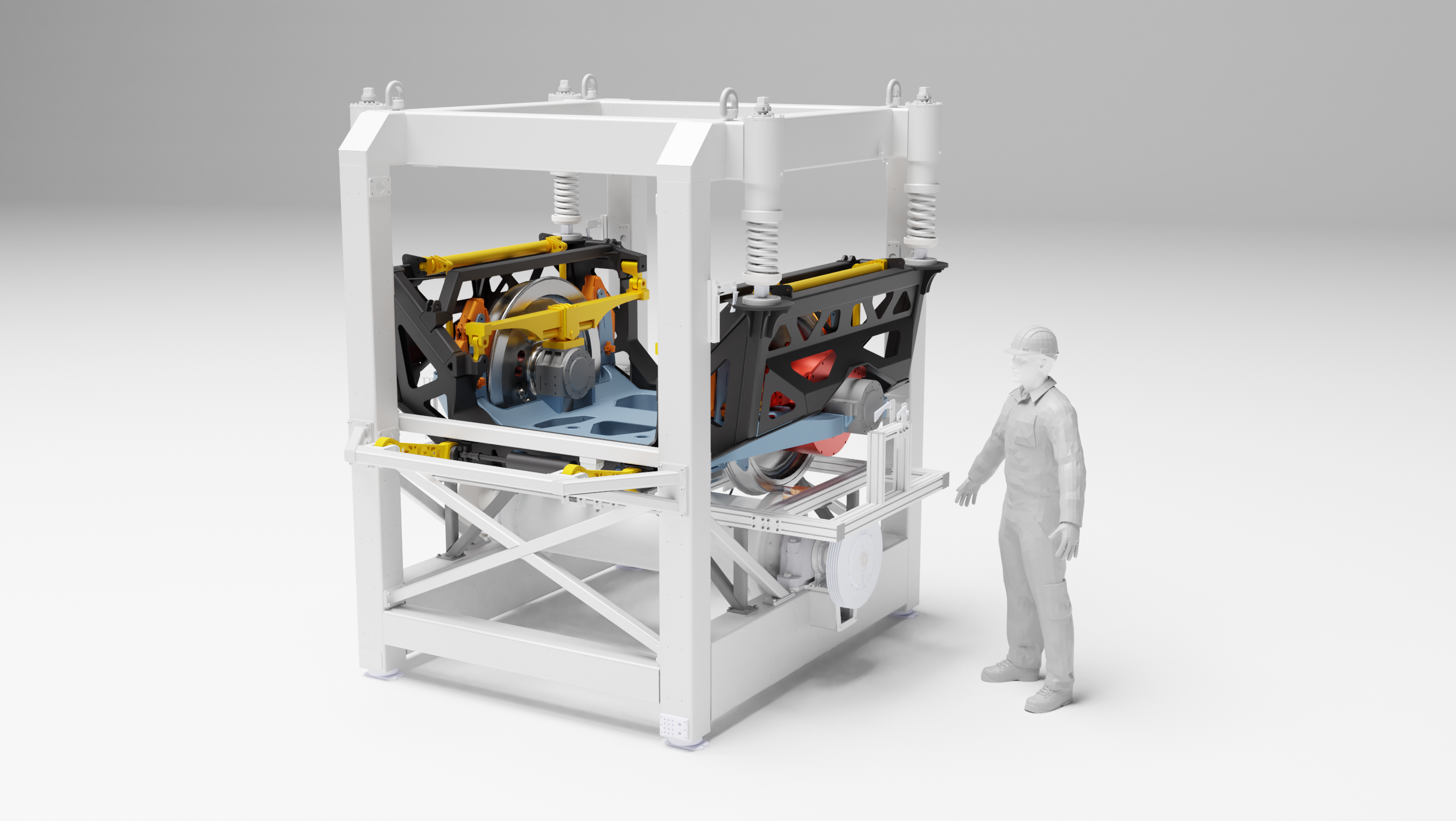
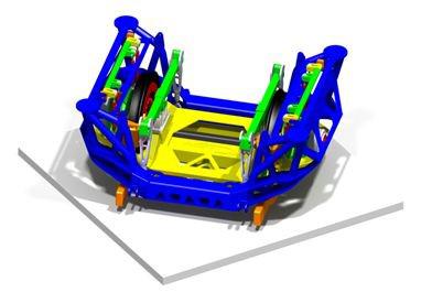
At the end of the current set-up phase of the NGT-FuN project in 2022, the M1:1 prototype of the NGT running gear will be available in an assembly and integration test rig. This setup, running gear in integration test rig, enables a simple, qualitative functional test of the sensors and actuators as well as the control and automation technology.
In addition to these qualitative experiments with largely reduced power supply, the setup is suitable for demonstrating the running gear principle to visitors in the laboratory or at an exhibition booth, e.g. at Innotrans 2022.
Currently, the design of the integration test rig is being virtually tested using multi-body simulation of the 4 different application scenarios:
- Scenario 1: Straight running of the running gear along the track center line
- Scenario 2: Straight running, but with lateral offset to the track center line
- Scenario 3: Artificial hunting motion, imposed by active control, with predefined frequency and running speed
- Scenario 4: Following a predefined and transient stochastic trajectory in order to emulate rail irregularities
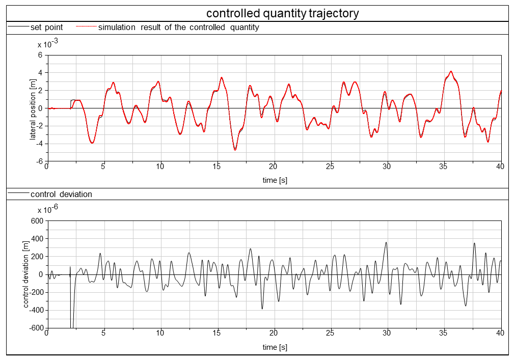
©DLR Simulation results of the setpoint and the actual trajectorie for the lateral position y and the yaw angle of the actively controlled running gear in Scenario 4.